 English
 简体中文
简体中文JIE intelligent transmission solution releases JIE intelligent transmission solution
complete information
Register / Login
Selection of the four major series of Jie JRT(R, F, K, S hard tooth surface reduction motors)
The four series of hard-tooth surface reduction motors (R, F, K, S series reducers) manufactured by JIE reducer (JIE) are famous brand transmission products with internationally advanced levels, mainly including JRTR series helical gear reduction motors, JRTF There are four series: parallel shaft-helical gear reduction motors, JRTK series helical gear-bevel gear reduction motors, and JRTS series helical gear-worm gear reduction motors.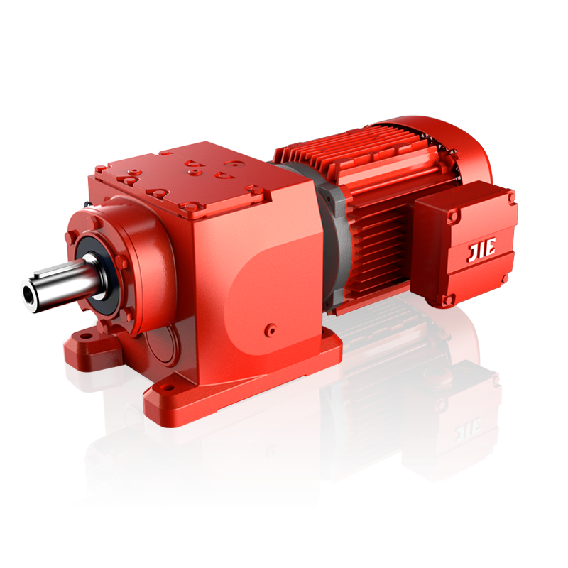
This series of hard tooth surface gear reduction motors follow the modular and optimized design concept, use finite element analysis technology, and adopt a unique low-noise gear tooth profile design to ensure the advancement of the design; the transmission ratio is finely graded and has millions of types Different combinations can meet various needs of users; everything from material selection to manufacturing is meticulous and strictly controlled - the box is precision one-time cast, beautiful and strong, and the gears are carburized and hardened, making them durable.
The four series of R, F, K and S reducers are processed in FMC flexible manufacturing units to achieve high precision and maintenance-free products. They are also equipped with double-type reduction motors (an additional helical gear reducer is installed at the input end), locking Discs, splined hollow shafts, B14 flanges and other combinations are available for customers to choose from.
| JRTR | F | 67 | II/G | D | 80 | N | 4 | /BMG /HF /TF | /128.97 | /M1 | /180° | |
| Code | 1 | 2 | 3 | 4 | 5 | 6 | 7 | 8 | 9 | 10 | 11 | 12 |
Code 1: refers to the product model code
JRTR--helical gear reduction motor
JRTF--parallel shaft-helical gear reduction motor
JRTK--helical gear-bevel gear reduction motor
JRTS--helical gear-worm gear reduction motor
Code 2: refers to the product assembly type
No code - foot installation
F--flange installation
..F--foot flange installation
M--flange mounting with extended bearing housing
X--foot-mounted single-stage transmission
XF--Flange mounted single-stage transmission
A--Hollow shaft installation
AF--flange hollow shaft installation
Code 3: refers to the specification number of the reducer
67, 17, 27, 37, 47, 57, 77, 87, 97, 107, 127, 137, 147, 157, 167, 177, 187
Code 4: Refers to flange size or torque arm accessories
None - no flange, or only one flange, or the minimum flange of more than one flange
II--The large flange among the two flanges, or the medium flange among the three flanges
III--the largest flange among the three flanges
G(T)--Torque arm
Code 5: refers to the electric motor
D--Three-phase asynchronous motor (IP54)
YB--explosion-proof three-phase asynchronous motor
YGP--Frequency control three-phase asynchronous motor for roller table (can be equipped with encoder)
YZP--frequency variable speed three-phase asynchronous motor for metallurgy and lifting (can be equipped with encoder)
YVP--Frequency control three-phase asynchronous motor (can be equipped with encoder)
YD--variable pole multi-speed three-phase asynchronous motor
Code 6: Refers to the motor specification code
80, 63, 71, 90, 100, 112, 132, 160, 180, 200, 225, 250, 280
Code 7: Refers to the code for the length of the motor stator core.
D,K,N,S,M,ML,L
Code 8: refers to the number of motor poles
4-pole motor, 6-pole motor
Code 9: Refers to accessory devices
None--No accessory device
BMG-brake
HF--manual release locked in brake release position
HR--manual release, automatic return to braking position
RS--backstop
TF - thermistor protection device PTC thermistor
TH--Thermostat protection device bimetal switch
U--body cooling (no ventilation)
V--forced cooling fan 3X380-415V 50HZ AC
VS--forced cooling fan 1X220-266V 50HZ AC
VR--forced cooling fan 1X24V DC
Z--High inertia flywheel fan
C--Fan protective cover (rain cover)
Code 10: refers to the transmission ratio of the reducer
Code 11: refers to the installation position of the reduction motor
M1, M2, M3, M4, M5, M6
Code 12: Refers to the location of the junction box
0°, 90°, 180°, 270°
popular
Authenticated user
followig
-
Authenticated user
-
Authenticated user
JIE intelligent transmission solution releases JIE intelligent transmission solution
-
- Sharing Center
- Member Sharing
- Exclusive Sharing
- Public Sharing
-
- Share
-


Official Website

Official Tiktok

Official WeChat
Copyright © 2022 Hangzhou Jie Drive Technology Co., Ltd. Zhejiang ICP No. 16044538-4

 Official Tiktok
 Official WeChat